|
|
||
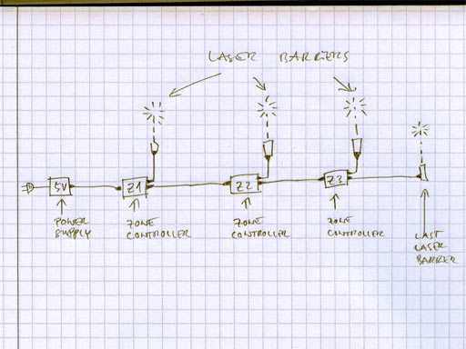
| Back to the diary | I have now started to build the Galleryzone system, that I've proposed in my diary entry from 25.8. This system will take care, that no Gallerydrive car crashes into another. It is highly flexible and modular. As many cars as needed can drive in the course. There exist three different types of Galleryzone devices: - The 5V power supply - The zone controllers - The laser barriers (- and the queue control unit - which works independently) All the Galleryzone devices are simply plugged together in a row. A simple schematic, how the devices are connected is shown below: |
|
|
||
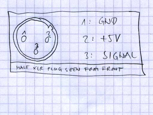
The used plug system is 3-pin XLR. The pins always have the same functions, so the system is quite idiot-proof: 1: GND For the zone controllers, I used a male socket for the connection to the previous zone (or power supply - if this is the first zone controller) and I also used a male socket for the connection to the next zone (or to the last laser - if this is the last zone controller). For the connection to the laser, I used a female socket. Each laser has a 2m cable with a male plug. |
||
|
||
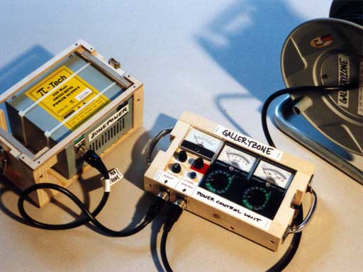
The whole connection of zone system devices starts with a 5V power supply, which is shown below: |
||
|
||
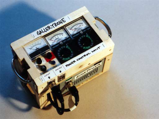
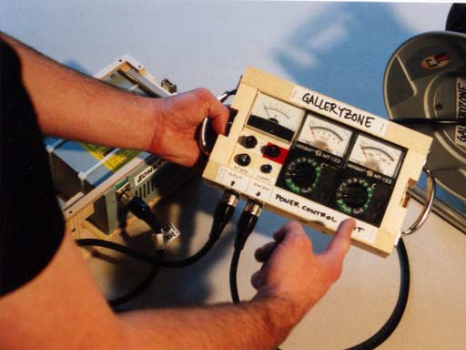
This power supply is a bit advanced and consists of two parts: The power supply itself (I used a PC switching power supply) and a power control unit - which is on top of it, but can be detached. |
||
|
||
The idea of the detachable power control unit is, that you can take it off and plug it somewhere in between the row of devices, to debug the system - if necessary. |
||
|
||
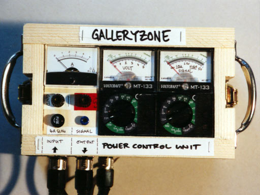
Let's have a closer look on the control unit. The three indicators show (from left to right): - The amperage, drained by all devices, which follow the control unit. - The voltage on the +5V power line - The voltage on the signal line Furthermore, this device can be used to branch 5V out of the system, or to provide the Galleryzone system externally with 5V, if the power supply doesn't work for some reason. The same can be done with the signal line: You can induct a signal voltage with this device, but you can also branch a signal voltage out of the system. |
||
|
||
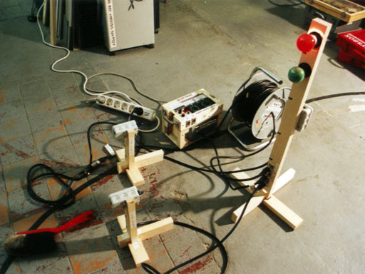
Here is a small one-zone setup, where I tried out the first zone controller. |
||
|
||
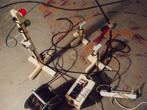
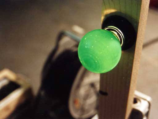
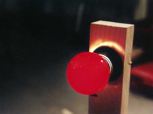
On the top right, you can see the two laser barriers, serving as a zone laser and a last zone laser. The thing with the red and green light bulb is the (unfinished) zone controller. |
||
|
||
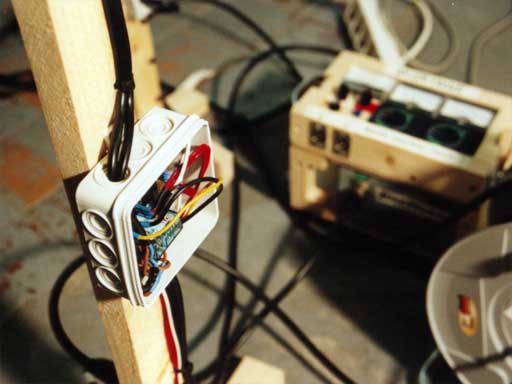
Here's the electronics of the zone controller. |
||
|
||
And this is the reason, why the zone controller is still unfinished: |
||
|
||
Because I really love the quality of the light of colored 230V bulbs, I decided to use them as visual indicators of the current status of each zone. But unfortunately, the induction, that happens, when the 230V bulbs are switched, confuses the microcontroller sometimes. Because of this reason and because - as Volker mentioned - it is somehow stupid to use 230V in parallel to the 5V circuit, I'll replace those bulbs by something working with 5V. But the light looks nice, heh? |
||
|
||
Please note, that the content on this webpage is licensed under a Creative Commons Attribution 2.0 License. Please respect the copyright of other webpages' content, which are linked from this webpage. |
||