|
|
||
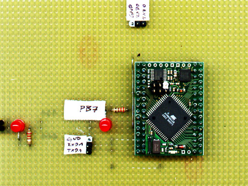
| Back to the diary | Because the ATmega128 microcontroller only exists in a SMD version, Dr. Erik Lins of chip45.com developed a very small and nice module, the Crumb128. It is basically an ATmega128 with some other useful parts on it: A MAX3221, to change RS232 TTL-signal-levels to real RS232. A CP2102 USB-UART converter (which I don't use), an external 14.7456MHz crystal and a status-LED, connected to PB7. The whole board can be mounted on a standard 2.54mm prototyping board. When I did the first test, I've read the info sheet of the module too fast. This was the reason, why I connected a status-LED to Portb.7 - it wouldn't have been necessary, because there is already one onboard. And I also did a mistake during the configuration of the fuse bits, when I tried to get the chip synchronized on the external 14.7456MHz crystal. By default it is synchronized by the much slower internal crystal). |
|
|
||
However, I misunderstood the very confusing fuse bit setting and set all the CKSEL[0..3] fuse bits to 0. The result was, that I couldn't flash the memory anymore and I also didn't have any chance to restore the lock- and fuse bit settings. To save the chip, I generated a 200MHz signal with an Atmega8. The next step was to connect the controller's XTAL1 pin to that signal. While most of the controller's pins are connected to one of the 2.54mm standard connectors, this pin wasn't. So I had to solder a wire directly to one pin of the ultra tiny controller. Without a proper SMD soldering iron, this was quite a task. I was already very lucky, that it wasn't necessary to remove the onboard crystal. It took some more experiments and some more emails between Dr. Lins and me, to find out, that the wire of my self built ISP programmer was too long and that the voltage, coming out of my Vaio's parallel port was too low. But when I've built a new ISP programmer with a short cable (40cm) and when I used an external 5V power supply, it all worked. Below, you can see a TwinAVR screen shot with the correct lock- and fuse bit setting for the ATmega 128 main controller. |
||
|
||
This seems to be the right place to show a screen shot of the lock- and fuse bit settings of the Atmega8 as well, which is used as drive controller. |
||
|
||
Please note, that the content on this webpage is licensed under a Creative Commons Attribution 2.0 License. Please respect the copyright of other webpages' content, which are linked from this webpage. |
||